Blog

Q&A
If Assembly Instructions, Application & Design Specs and our Product List are of interest, you probably have questions about damped machining tool holder selection, installation, troubleshooting and more. That’s why we’ve complied a list of FAQs that should help you get the most out of your damped machining tool.
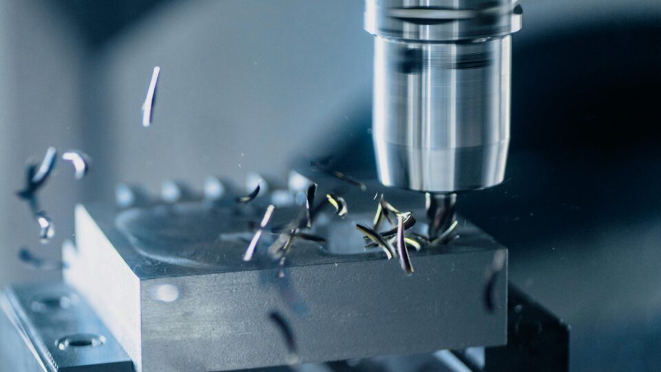
All machine tools vibrate when the turning or milling insert engages with the workpiece. The machining tool naturally vibrates at certain frequencies when it’s cutting a workpiece. That will result in bumping surface marks on the workpiece. In most cases, the bumping surface marks excite the tool holder structure with a frequency near the natural frequency of the structure. That is where the structure is the weakest. The regenerative tool chatter refers to the situation where the machining process is chaotic in regards to vibration, and the vibration increases over time as the machining process continues.
Vibrations occur in all kinds of metalworking processes. The cutting tool performance will be affected by the vibrations. Since machining vibration is something you won’t be able to eliminate, you need to find ways to reduce it. Reducing vibrations means better tool performance, higher production speed, substantial savings, and a better surface finish.
A method to absorb the vibrations occurring between a tool and a workpiece. (In the metal cutting industry known as tool chatter). Vibration damping normally transforms the vibration energy into thermal energy/heat. A mass damper will firstly transfer the vibration energy from the cutting tool to the heavy mass and then transform the vibration energy into thermal energy. Vibration damping technology will reduce the risk of production stops and improve the surface finish on the machined parts.
A self-tuning mass damper (STMD™) tool holder is a tool in which the stiffness support of the mass inside automatically adjusts to the vibration frequencies in metal cutting operations. MAQ is the first company to develop a self-tuning mass damper tool holder. When vibration occurs, the self-tuning mass damper tool will assist to transfer the vibration energy from the cutting tool to the mass damper, and then dampen/transform the vibration energy on the mass damper into heat / thermal energy.
Many providers offer tuned mass dampers tool holders. Either these solutions are pre-tuned to a determined frequency, or you have to fine-tune the tool holder during the machining process. MAQ’s STMD™ tool holder is the only solution that self-tunes to the frequency in the machining operation.
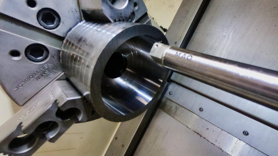
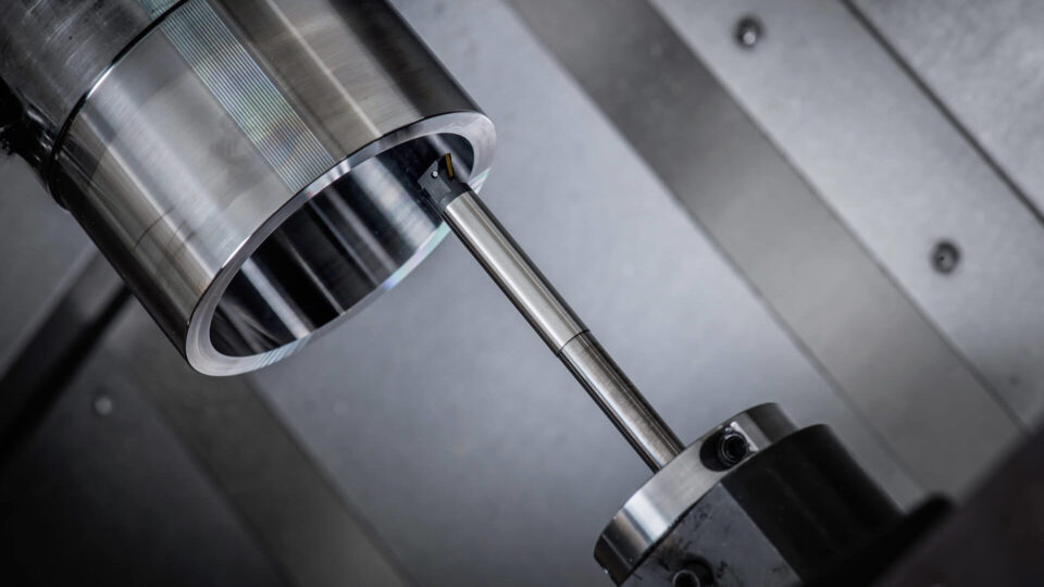
Our vibration damped tool holders have standard dimensions with or without a standardized connection design. To install one of our vibrations damped turning tool holders with a straight cylindrical shape, you should use a standard adapter for mounting the tool, via means of reduction sleeve, all around clamping, hydraulic clamping, or shrink-fit clamping. When installing a damped turning tool holder with a tuned mass damper inside, avoid using screws for direct mount to engage with the tool holder’s surface. That is because direct contact may damage the dampening system. The direct screw mount also has a low bending stiffness/rigidity.
We recommend using cooling media (lubricant, emulsions, or compressed air) when using MAQ’s vibration damped tool holders. To maximize the effectiveness of your tool holder, it should never operate at a temperature above 100°C (212°F). Overheating reduces effectiveness and accelerates the aging of the tool holder’s internal components.

Lorem ipsum dolor sit amet, consectetur adipiscing elit, sed do eiusmod tempor incididunt ut labore et dolore magna aliqua.